Week Eight (May 19, 2016):
Objectives:
- Test heat pipe with 45.7 mL
- Gather data from fourth test
- Evaluate data
- Begin thinking about the final design
Detailed Description:
This week the final test will be performed. For this test, the pipe will be approximately 17% full of water. Seventeen percent equals about 45.7 mL. This number was decided on because it is the mid point between the first test (32 mL) and the second test (68 mL).
After the test, it appeared that positive results were collected. However, the data does not appear to show any trends when compared to previous tests.
Results:
Data Table:

Plot:

Week Seven (May 12, 2016):
Objectives:
- Test heat pipe with no water used (Control Run)
- Gather data from third test
- Evaluate data
- Contemplate improvements that can be made for the heating pipe
Detailed Description:
This week a dry run with 0 mL of water was performed. The pipe was also filled to seventeen percent of the pipe's volume in preparation of week 8. Seventeen percent is about 45.7 mL. The idea for this test was to figure out how much of the cooling is being done by just the pipe instead of the pipe with water.The results showed that there was still a large difference in temperatures between the evaporator and the points higher up on the pipe. There was a smaller difference in temperature between the bottom of the heat sinks and the top of the heat sinks. This test showed that water plays an integral part in the performance of the heat pipe.
Results:
Data Table:

Plot:

Week Six (May 5, 2016):
Objectives:
- Continue testing the heat pipe
- Continue experimenting with different volumes of water
- Gather data from second test
- Evaluate data
- Contemplate improvements that can be made for the heating pipe
Detailed Description:
After the positive results from last week, it was hypothesized that adding more water could improve the performance of the pipe. Essentially the volume of water was doubled for the next test. Last week 32 mL was used last week and 68mL was used for the test this week. The results this week were slightly worse than last weeks. However, a control test still needs to be done. Next week, a dry run and a run where seventeen percent of the pipe is filled will be performed. Seventeen percent is about 45.7 mL.The data gathered from the second testing of the heat pipe proved to be less successful compared to the first. The "hot end" of the heat pipe was hotter than the "cold end" of the heat pipe, but the temperature difference was smaller than last week's. For this test, 68 mL of water was used. More experimentation with different volumes of water will have to continue to find the volume of water that maximizes efficiency.
Results:
Data Table:

Plot:
Week Five (April 28, 2016):
Objectives:
- Begin testing the heat pipe
- Experiment with different amounts of water
- Experiment with different sized wicks
- Gather data from first test
- Evaluate data
- Contemplate improvements that can be made for the heating pipe
Detailed Description:
This week started of with a discussion about the minute details such as the size of the wick and the amount of water that should go in the pipe. It was decided to experiment with different combinations of the two to see which ones performed most efficiently.After this discussion, copper mesh wick and water were added to the pipe and the pipe was sealed shut.
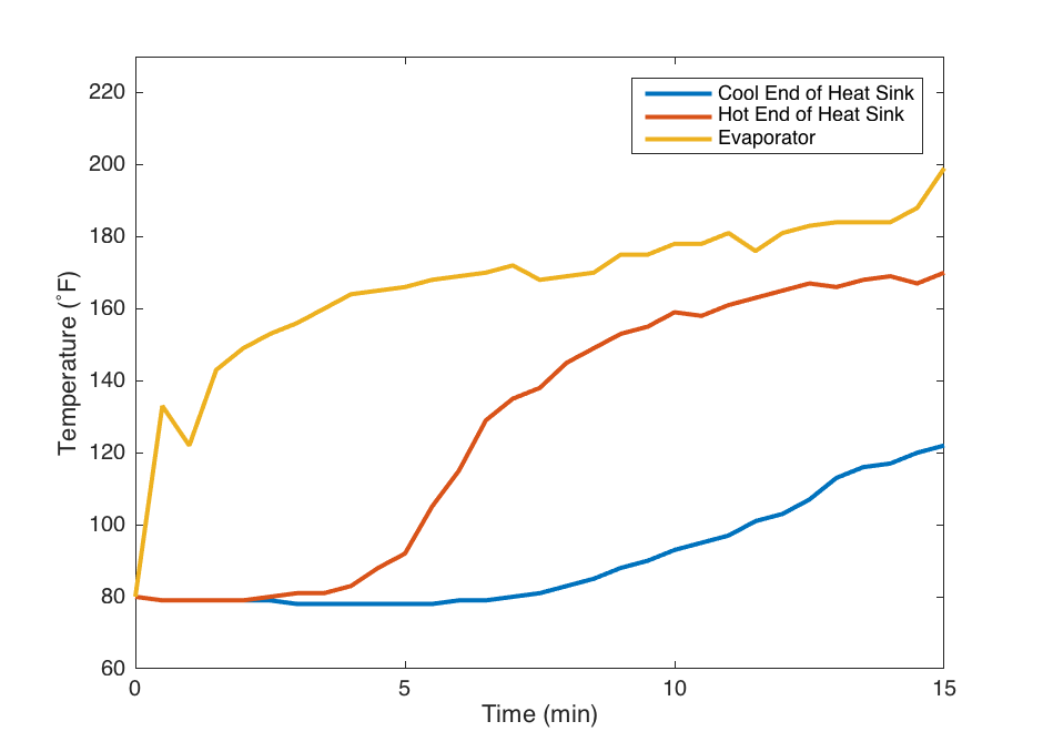
Toward the end of the lab period, the heat pipe was tested for the first time. The heat pipe was heated for approximately 10 minutes at 500˚F. The heat pipe seemed to perform well and the heatsinks dissipated a majority of the heat. Even by the end of the run, there was a 80˚F temperature difference between the beginning and end of the heatsink region. The condensing end of the pipe also never exceeded 200˚F indicating that it was never overwhelmed to the point where it could no longer function as efficiently.
One small issue experienced was that toward the end of the run, the evaporator end of the pipe exceeded the boiling point of water. This could mean that all of the water was evaporating faster than it could recondense and return to the evaporator. This should not occur if a constant phase equilibrium is present in the pipe. In order to remedy this issue, the pipe will be tested again with more water inside.
The data gathered from the first testing of the heat pipe proved to be successful. The "hot end" of the heat pipe was hotter than the "cold end" of the heat pipe. As well, the heatsink temperature was warmer at the hot end for the heatsink than the cold end. For now, the only improvements that can be made is adding more water to get more accurate results. For the test, 32mL of water was used.
 |
| Figure 3a: Device used to heat the pipe |
 |
| Figure 3b: Testing the effectiveness of the heat pipe |
Results:
Data Table:

Plot:

Week Four (April 21, 2016):
Objectives:
- Finish constructing the heat pipe
- Prepare for testing next week
- Start researching equations that will be useful for temperature calculations
Detailed Description:
This week, construction of the heat pipe will end. The coupling holding both pipes together still needs to be soldered. Heat sinks also need to be placed on the upper pipe and they will be set into place using thermal paste (Figure 2). After the pipe is soldered, copper mesh will be pushed in through the top. As mentioned before, the copper mesh will act as a wick. Once those tasks are completed, the preliminary design for the heat pipe will be completed and testing of the pipe may begin.
Equations will be needed to witness how efficiently the heat pipe works. This will be done through an equation that calculates thermal spreading resistance. The equation is as follows:
R = (T - M)/q
Where T is the maximum temperature, M is the reference temperature, and q is is the given heat transfer rate for the center of the heat input area.
 |
| Figure 2: Heat sinks being paced on to the upper pipe |
Week Three (April 14, 2016):
Objectives:
- Get group members certified in the machine shop
- Begin manufacturing the heat pipe
Detailed Description:
It was determined that Mark, Liam, and Shawn would be certified in the machine shop. This week, they began manufacturing the heat pipe. The air chambers were cut and joints were welded on.
Since the last lab, fifteen aluminum heat sinks (Figure 1b) were purchased. The goal of the heat sinks is to distribute the heat and allow it to cool faster. Mark proposed putting another tube around the heat sinks and a fan to draw the heat off the heat sinks even more. The heat sinks ordered were designed for use in transferring heat away from large LEDs. Because of this, they came with small prongs in the middle ring that needed to be removed and filed until smooth.
Additionally, copper mesh (Figure 1c) was purchased for use as the heat pipe wick. This mesh should act to direct condensed water back to the evaporating section of the heat pipe.
Shawn made a CAD model of the heat pipe in Fusion 360 (Figure 1a).
 |
| Figure 1a: Fusion 360 model of our heat pipe design |
 |
| Figure 1b: Aluminum heat sinks |
 |
| Figure 1c: Copper mesh |
Week Two (April 7, 2016):
Objectives:
- Have a unified idea as to what the heating pipe should look like
- Determine which group members will be certified in the machine shop
Detailed Description:
Since the lab from Week One, the idea for the design of the heating pipe was divided. Some members wanted the pipe to be bent, some members wanted different metals to be used, and some members wanted different liquids to be used. Though the idea may change, the tentative final pipe design includes two copper pipes, one with a compressed end pipe, welded together with either copper or galvanized steel. A screw plug will be welded to the top of the pipe so the amount of water can be adjusted. Aluminum heat sinks will be on the top of the pipe to help dissipate heat. All of the piping and joints were bought from a local hardware store. The heat sinks were ordered and should arrive by next week.With a majority of the work needed to be done in the Machine Shop, at least one group member must be certified to work in the Shop. Liam volunteered to get certified in the Shop, with the possibility of Mark getting certified as well. Optimally, Liam will be certified before Week Three, but the project will remain on the same timeline if he is certified by Week Four.
Week One (March 31, 2016):
Objectives:
- Group Formation
- Obtain Information about Heating Pipes
- Form a List of Materials
- Begin Discussing Design of Pipe
Detailed Description:
All objectives for this week's lab were met. The formation of the group was decided prior to the beginning of class, consisting of Liam Cummings, Kimberly Leyzerzon, Douglas Meadowcroft, Shawn Mengel, and Mark Rad.The main focus for this week's lab was to obtain information about heating pipes. More specifically, what liquid would be best to use as the working fluid, how much liquid should be used, what metal would be the best at conducting heat, and what shape and size the heating pipe should be. Given predetermined parameters of the pipe being heated to a range of 250 - 500 degrees Fahrenheit, a substance must be able to stay in a dynamic equilibrium between the gas and liquid phases. As well, the pipe must be able to withstand this temperature range and remain a solid. With these parameters in mind, water will be the liquid being heated and it will be enclosed by a copper pipe. In total, the materials that will be used in this project may include, but are not limited to:
- Water
- 3/4 inch galvanized plug
- 1 inch x 3/4 inch copper adapter
- 1 inch copper nonstop coupler
- 3/4 inch galvanized coupling
- 1/2 inch x 12 inch air chamber (2)
- 1 pound copper mesh
The design of the pipe was discussed in a rudimentary fashion; however, a basic idea was formed for the building of the pipe. Theoretically, it will be fully closed on one end and have the ability to open on the other end. The plug will be welded on the pipe and will act as a pressure stabilizer. The mesh will act as the wick on the inside of the pipe.
Missing group 9 activities.
ReplyDelete